


Rapid Results with Simple LED IVL Characterization
A long-lasting, low cost LED characterization and lifetime measurement system
| | | | | | |
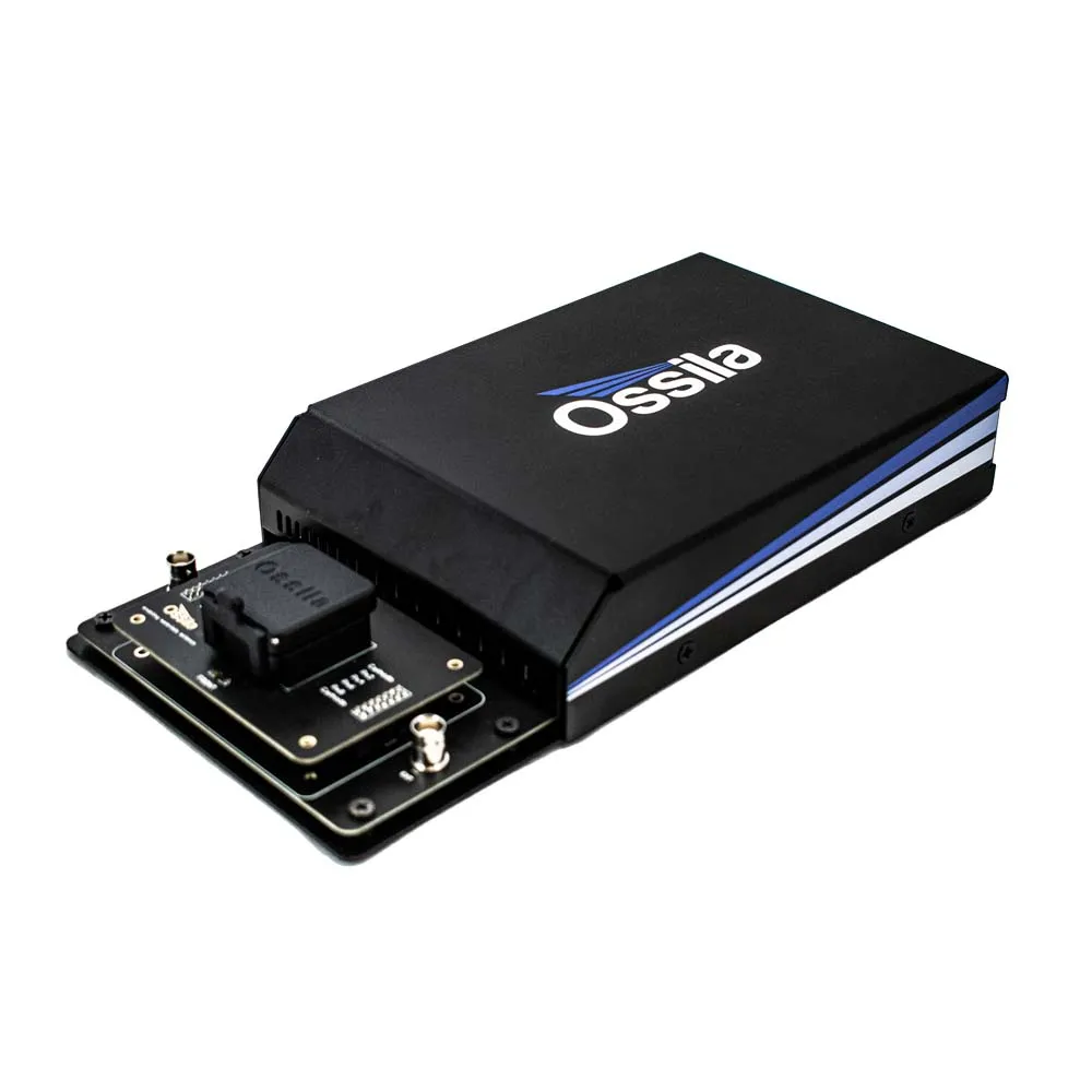
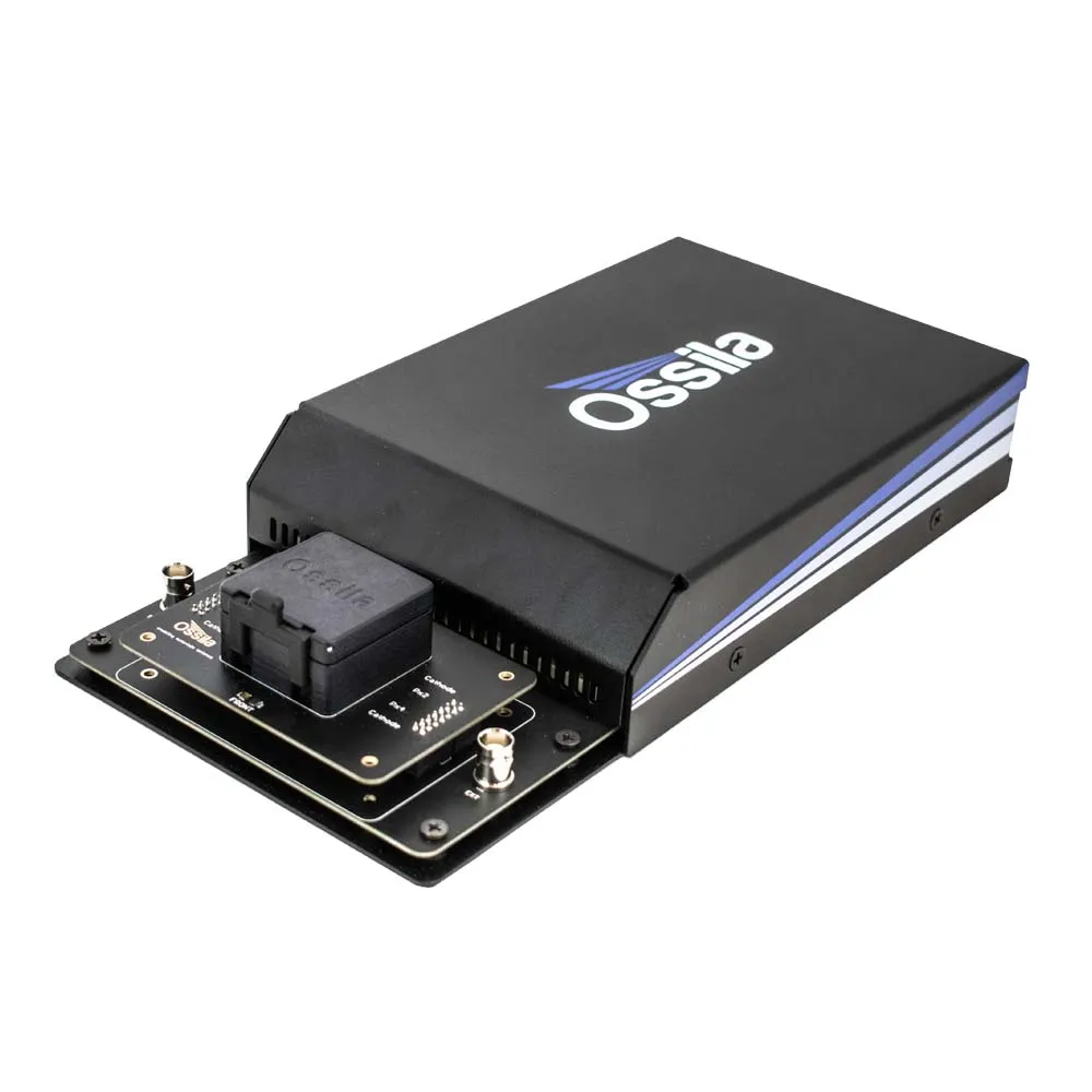
The Ossila LED Measurement System provides a low cost and complete solution for performing current-voltage-luminance (IVL or JVL) characterization of LEDs. The device holder has built-in light sensors to allow for illuminance, luminance, and white count measurements. To simplify device testing, the software will also calculate the current and power efficiency of your LED. Lifetime mode, meanwhile, measures the performance of the LED over an extended time under a constant voltage.
The system is compatible with all Ossila substrate systems, so it is easy to both fabricate and test LED devices.
Two-Year Warranty
Buy with confidence
Compact Design
Fits in any lab
LED Measurement
Complete measurement solution
Free Software
Intuitive PC software included
Looking for the Ossila OLED Lifetime Measurement System?
The LED Measurement System replaces the OLED Lifetime Measurement System. The new device holder and upgraded software package together add support for new characterization measurements, but it is still easy to take OLED lifetime measurements with the LED Measurement System. If you are looking for a manual device, consider the Ossila .
Specifications
| Wavelength Range | 400 nm – 1050 nm |
|---|---|
| Substrate Size | 20 mm x 15 mm (0.79" x 0.59") 25 mm x 25 mm (0.98" x 0.98") |
| Substrate Compatibility | T2005B - T2005E - |
| Overall Dimensions (W x H x D) | 151 mm x 50 mm x 300 mm (9.94" x 1.97" x 11.81") |
What is an IVL (or JVL) measurement?
IVL, or current-voltage-luminance, is the main method for electrically characterizing light emitting diodes (LEDs). In IVL measurements, the current (I or J) passing through a device and the emitted light are measured as an applied voltage (V) is swept between two points. From this measurement, multiple properties can be determined, including the luminance (L), current efficiency, and power efficiency (also known as efficacy).
LED Measurement System Features
Rapid Characterization
Our intuitive software (included) makes it easy to take current-voltage-luminance measurements. The system records illuminance, luminance and white count. To speed up the characterization process, the system will then calculate both the current efficiency and power efficiency of your LED.
Wide Measurement Range
The built-in Source Measure Unit is capable of delivering voltages between -10 V and 10 V, with a maximum resolution of 170 μV, measuring currents from as low as ±10 nA up to ±200 mA, and illuminance up to 100 klx.
Intuitive Software
Create and save settings profiles, plot your data in real time, and export the results as a CSV file. Data is plotted in real-time as it is measured, with the ability to select which data is plotted on each y-axis. Create individual settings profiles to quickly and easily repeat your measurement or perform similar scans.
Measure Device Stability
By applying a constant voltage and measuring the current, luminance, and efficiency over an extended period of time, the stability of LEDs can be tracked and analysed.
Quick and Easy
Plug in the system, install the PC software, and you're ready to go! The Ossila LED Measurement System has been designed by research scientists to address the frustrations associated with measuring and characterizing LEDs. The intuitive interface and clean design make the system simple and easy-to-use.
LED Measurement System Gallery
Software
The LED current-voltage-luminance measurement is controlled using intuitive and user-friendly PC software. All of the measurements can be fully customized so that you can tailor the software to your experiment.
The software has two measurement tabs: characterization and lifetime. Characterization mode performs I-V measurements of LEDs while measuring the illuminance, luminance, white count, and calculating the current and power efficiencies. The lifetime mode enables you to set a constant voltage and measure the performance of the LED over an extended time.
In the Box
- Ossila LED Measurement System
- USB-B cable
- 24 VDC power adaptor
- LED IVL Software
Accessories and Related Products
[[collection handle="substrates-and-fabrication" tags="spectroscopy" limit="4" show-more="false"]]


![Analytic Systems Waterproof IP66 DC Battery Charger 10A, 12V Out, 20-80V In, Ruggedized [BCH10W-12]](https://www.wireleashome.shop/image/analytic-systems-waterproof-ip66-dc-battery-charger-10a-12v-out-20-80v-in-ruggedized-bch10w-12_SconR8_285x.webp "Analytic Systems Waterproof IP66 DC Battery Charger 10A, 12V Out, 20-80V In, Ruggedized [BCH10W-12]")


